Advanced Measurements & CAD Compatibility

Our Virtual Tours include CAD Compatible Floor Plans with optional an Advanced Measurements option for tours that will be used in building 3D Models.

Q: Are your Floor Plans CAD Compatible?

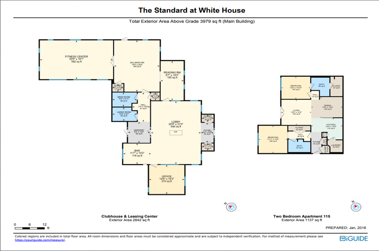
A: YES. The 2D Floor Plans are CAD compatible. The DXF file is included in the Offline-iGUIDE download, and can imported into CAD programs. A 3D CAD Model can be created from 2D Floor Plans by extruding them upwards using ceiling & door heights as well as windows using Virtual Tours that have the Advanced Measurements option added to the project.

Alex Likholyot – Planitar Employee (iGUIDE) Dec ’19

The iGUIDE camera captures a dense 2D point cloud that allows the creation of accurate 2D floor plans that are available in DXF CAD format as well. A 3D CAD model can easily be created from 2D floor plans by extruding them upwards and using ceiling and door heights, as well as heights and elevation of windows that can be obtained through iGUIDE’s newly released 3D Advanced Measurements Modes. This would not be an automated process, however, an architect could easily do it without having to leave the office.

Examining other 3D cameras, such as Matterport, Occipital (https://canvas.io or https://structure.io, as used by GeoCV) or the just announced Intel’s time-of-flight lidar camera (https://www.intelrealsense.com/lidar-camera-l515), they produce a 3D point cloud. That 3D point cloud is turned into a 3D model by computing a triangular 3D mesh, where the size of triangles can be quite big at large distances away from the camera or due to optical occlusion by furniture. Triangles size limits the fidelity of the 3D model and accuracy of any 3D measurements that are made using that model. Look at any Matterport dollhouse to see how rough the mesh really is.

Matterport measurement of a lamp

Matterport 3D Measurements

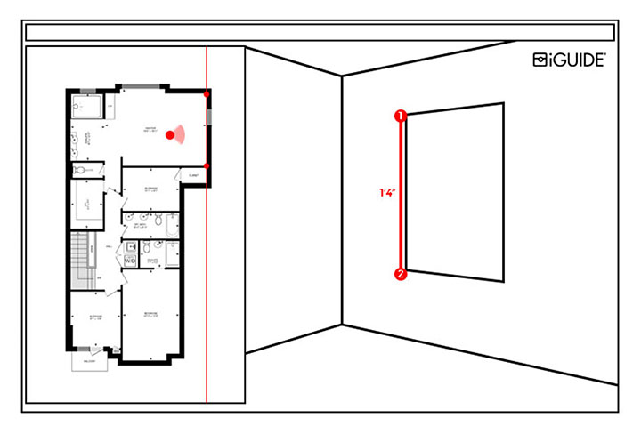
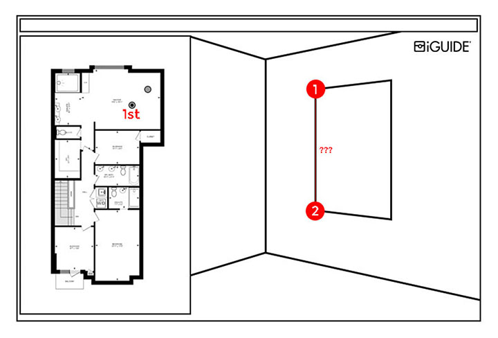
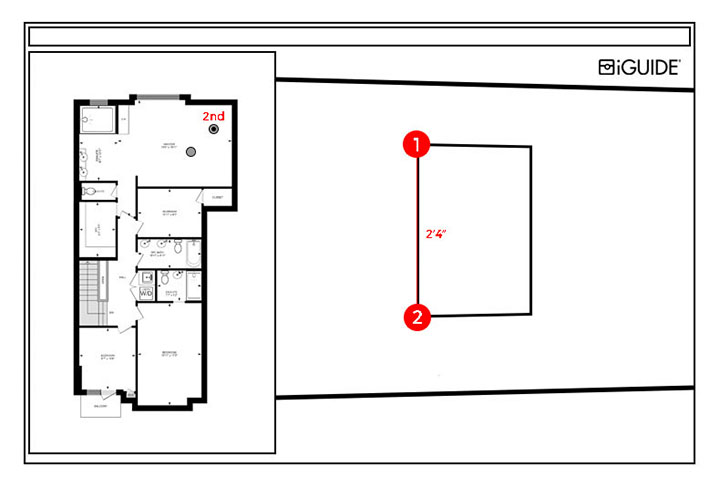
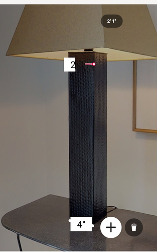
Experiment with the just released Matterport’s 3D measurements to see how limited and inaccurate the 3D mesh can be (https://try.matterport.com/measurement-mode/) - the lamp is measured to be 4" at the base and 2’1" at the top.

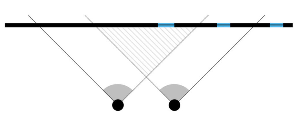
Using multiple panos per room and photogrammetry, we can create a 3D mesh from iGUIDE images, similar to how Cupix does it from 360 cameras or 360 images. But as seen above, that mesh can be quite rough and the measurements can be quite inaccurate. To get a finer mesh, it would take an exponentially longer time using a handheld 3D scanner (like Occipital’s or Intel’s) and would need to be used to “paint” walls and objects with it from a close distance.

In contrast to this, the way our new 3D measurements work does not rely on a complex 3D mesh, but uses the direct measurement points you select, which allows us to also report the estimated uncertainty of each 3D measurement.

iGUIDE 3 advanced measurement modes

iGUIDE Advanced 3D Measurements

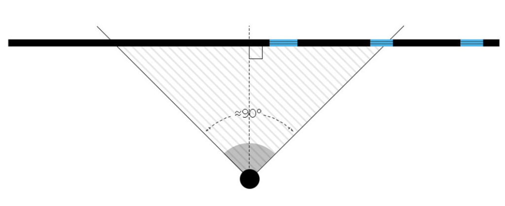
iGUIDE recently added the option for Advanced Measurements to their tour technology, which enables a viewer to take on-screen measurements within the Virtual Tour Viewer. If your project needs the most CAD Compatibility, either order a Premium Virtual Tour Package or add the Advanced Measurements Option to your project from the "Extras" section of the order form.

The Advanced Measurement Tool has 3 Modes. 

Standard measurements (Mode 1) are featured in every 3D Virtual Tour Package by default.  

Advanced Measurements (Modes 2 & 3) are featured as part of every Premium 3D Virtual Tour Package, but can also be added as a paid add-on to Standard Tour Packages as well.

If your project needs Advanced Measurement Features, please be sure to add the option to your 3D Virtual Tour Package as the process of mapping the space for 3D Modeling is more detailed to allow for more accurate CAD/DXF data and adds about 20 minutes of on-location time.

Using the Measurement Tool

Here are the Instructions on how to use Measurement Modes 1, 2, and 3 and watch the video on how to use the measurement tool:

Mode 1 – Basic Measurements on Floor Plan

Measure the horizontal distance between any two points on the floor. This mode is useful for measuring wall to wall distances in irregularly shaped rooms or to see if your furniture will fit.

To use this feature, select Measure Mode 1, then click and drag from one point to another on the floor plan. A red line will connect the start and endpoints and its length will be reported as shown in Figure 1.

Advanced Measurements Mode 1 F1
Figure 1. Basic Measuring

Mode 2 – Measurements on a Vertical Plane

Measure the distance between points located on a vertical plane using a panorama. This mode is useful for measuring features found on walls, such as windows, doors, and ceiling height.


To use this feature, select Measure Mode 2, then click and drag from one point to another on the floor plan to draw a line segment. It will get extended into an infinite line, shown in red, on the floor plan as seen in Figure 2. When projected upwards from the floor, that line will define a vertical plane. All subsequent measurements will be reported as if the points selected in a panorama were located on the plane. Most of the time that plane will be the front surface of a wall visible from the panorama. Click on any two points in the panorama to measure the distance between them. You can zoom in to the panorama for more precise positioning. 


The two points must be located on the vertical plane you defined, otherwise the reported distance between them will be meaningless.

Advanced Measurements Mode 2 Measuring a Vertical Plane F2
Figure 2. Measuring a Vertical Plane

Mode 3 – Dual Panorama Triangulation


Measure the distance between any two points in 3D space by using two panoramas. The two points must be clearly visible in both panoramas. This mode is useful for measuring distances that cannot be measured using Mode 1 or Mode 2.


To use this feature, select Measure Mode 3, then select the first panorama that contains the two points of interest and click on those points, remembering the order in which you do that, as shown in Figure 3. You can zoom in to the panorama for more precise positioning. The distance between the two points will initially be shown as “???”. Next, select the second panorama and click the same two points of interest in the same order. You can use zoom again for greater precision. The measurement will appear instead of the three question marks after all four points have been selected, as seen in Figure 4


It is very important that both panoramas were shot with a camera located on the same horizontal plane (no split-level floors should be used) and using the same tripod height, otherwise, the reported distance will be meaningless.

Figure 3. Measuring in 3D space - view from the 1st panorama
Advanced Measurements Mode 3 - Dual Panorama Triangulation - F4
Figure 4. Measuring in 3D space - view from the 2nd panorama

Multiple Measurements and Undo


You can make multiple measurements in Modes 1, 2, and 3 – just keep selecting new additional points. You can use the Undo button to delete the last point. In Mode 3, Undo will work only until a new pano is selected.

Reducing Measurement Uncertainty


After completing a measurement in Modes 2 and 3 you will receive a message that looks similar to this when a measurement has been taken:


“Estimated measurement uncertainty is 2. Take additional measurements by selecting new start and endpoints.”


The measurement uncertainty will vary depending on the panoramas selected and the measurement points chosen. Reduce the measurement uncertainty to the lowest possible number by trying the same measurement multiple times, using different panoramas to see what yields the best results.


When choosing a panorama in Mode 2 try to use a panorama that is close to features you are trying to measure. This makes selecting the features easier and will reduce measurement uncertainty. This can also be expressed as keeping measurements within a 90° field of view when the panorama’s viewing direction is perpendicular to the vertical plane in which measurements are taken. See the shaded area in Figure 5.

Advanced Measurements Keep in Shaded area

When using Mode 3, try to choose panoramas that are close to the features being measured, but that are far enough apart from each other to offer a unique and different perspective. Try to keep measurements out of the periphery of either panorama to reduce measurement uncertainty and aim to keep measurements within the shaded area in Figure 6.

Advanced Measurements Overlapping Measurements

Video of how to use the Measurement Tools

NOTE: We are NOT responsible for YouTube’s “Suggested Videos” at the end; YouTube decides for you based on your activity.

Share